R-6.0
Note: Installation instructions and illustrated drawings are recommendations only, while proper local construction methods are the responsibility of the installer.
Reflectix® Duct Insulation is an alternative to other types of fibrous insulation products. Ease of handling and quick installation make Reflectix® the first choice when selecting insulation for round or rectangular ductwork in HVAC systems. The product provides an R-6.0 when installed with a 0.75” air gap between the duct and the insulation. There is a choice of three spacer configurations that create the required air space.
Product Description
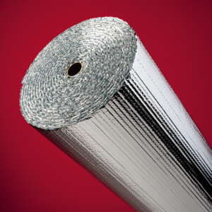
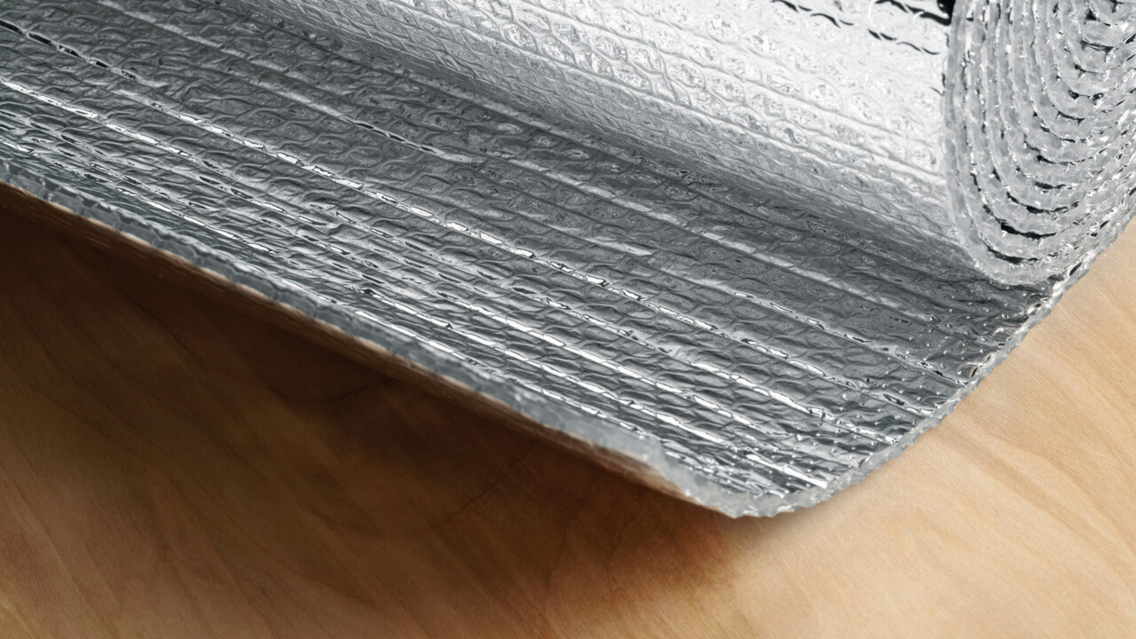
Reflectix® Duct Insulation consists of two layers of highly reflective film (96% reflectivity) that are bonded to two tough layers of polyethylene. Two inner layers of insulating bubbles resist conductive heat flow while a center layer of polyethylene gives Reflectix® high reliability and strength. The product has a tape running the length of the roll for easy identification by code officials. The tape identifies the manufacturer and ASTM Testing: Reflectix® Duct Insulation • ASTM E84 • Class A / Class 1 • ASTM C411 Passed
Benefits
- Wrap rectangular or round ductwork in HVAC applications
- Heating costs can be greatly reduced
- Eliminate unnecessary heat loss / gain and air leakage
- Helps to ensure consistent temperatures
- Non-toxic / non-carcinogenic
- Fiber-free
- Lowers heating and cooling costs year-round
- Reflects 96% radiant heat
- Costs less to install
- Lightweight and clean
- Not affected by moisture / humidity
- Does not promote nesting of insects or rodents
- Resists growth of fungi, mold and mildew
- Does not require protective clothing or respirators to install
- ISO 9001:2015 certified manufacturing location
Part Numbers and Sizes
- HVBP12050 (12”x 50’)
- HVBP16050 (16”x 50’)
- HVBP24050 (24”x 50’)
- HVBP36050 (36”x 50’)
- HVBP48050 (48”x 50’)
- HVBP60050 (60”x 50’)
- HVBP12100 (12”x 100’)
- HVBP16100 (16”x 100’)
- HVBP24100 (24”x 100’)
- HVBP36100 (36”x 100’)
- HVBP48100 (48”x 100’)
- HVBP60100 (60”x 100’)
- HVBP12125 (12”x 125’)
- HVBP16125 (16”x 125’)
- HVBP24125 (24”x 125’)
- HVBP36125 (36”x 125’)
- HVBP48125 (48”x 125’)
- HVBP60125 (60”x 125’)
Spacers:
- HVSP0202506
- HVSPACER
Technical Data
- Temperature Range: -30 to 180 F
- Nominal Thickness: 5/16 inch (.312)
- Weight: 0.771 oz./sq. ft.
- Flame Spread Index (ASTM E 84): Less than 25
- Smoke Developed Index (ASTM E 84): Less than 50
- Fire Rating: Class A/Class 1
- Linear Shrinkage: None
- Reflectance (IR): 96%
- Water Vapor Transmission (ASTM E 96): 0.02
- Puncture Resistance: 60 lb./in.
- Mold and Mildew: No Growth
- Emittance: 0.04
- Tensile Strength: 3.7 N/mm
- Pliability: No Cracking
- Hot Surface Performance: Passed (250 F)
Note: Not for use in direct contact on surface temperatures that are 180 F or greater.
Testing and Certification
- Thermal Performance ASTM C335
- Hot Surface Performance ASTM C411
- Flame Spread and Smoke Density ASTM E84
- Fungus Resistance Mil-Std 810B Method 508
- Pliability Test ASTM C1224
- Water Vapor Transmission ASTM E96
- Tensile Strength ASTM D751
- Bleeding and Delamination ASTM C1668
- Intertek: Surface Burning Characteristics of Building Materials ASTM E84-08 (Taped Joint Detail) Test Report # 3166908SAT-012
- Intertek: Surface Burning Characteristics of Building Materials ASTM E84-08 (Unslit) Test Report # 3166908SAT-011
- R&D Services: Resistance to the Growth of Fungi ASTM C1338-00 Test Report # RD072713FR
- State of California
- State of California Licensed Insulation Manufacturer
- State of Minnesota: Filed with Minnesota Insulation Standards Program
- R&D Services Emittance Testing ASTM C1371
- R&D Services: Physical Properties Sheet Width, Length, Pliability, Water Vapor Permanence and Aged Water Vapor Permanence
- R&D Services: Water Vapor Transmission Test ASTM-E96 (Dessicant Method)
Installation Instructions
Note: Installation instructions and illustrated drawings are recommendations only, while proper local construction methods are the responsibility of the installer.
1. Spacer Perpendicular to Duct Direction Method
Spacer: HVSPW02025 – Reflectix® Spiral Pipe Wrap 2”x 25’
- Refer to the top two diagrams above.
- Make sure all sheet metal joints, seams and penetrations are sealed.
- Double wrap and secure spacer material to the duct at 24” to 36” intervals. Use a UL 181 approved tape to fasten the spacer in place.
- Verify the circumference of the duct at the mid-point of a spacer strip.
- Cut the Reflectix® product to this length plus 1”.
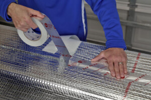
- Wrap the product around the duct and securely tape the linear and circumference seams (overlapping 1”- 2”) with a UL 181 approved tape (goal is an air-tight, snug seam seal).
- Do not leave any exposed duct or space where air can enter between the duct and the Reflectix®.
2. Spacer Wrapped in Candy Cane Fashion Method
Spacer: HVSPW02025 – Reflectix® Spiral Pipe Wrap 2”x 25’
- Refer to the third and fourth (from the top) diagrams above.
- Make sure all sheet metal joints, seams and penetrations are sealed.
- Double wrap and secure spacer material to the duct in a candy cane fashion. First, proceed down the duct in one direction then reverse direction and crisscross (overlap) the spacer in the other direction. Use a UL 181 approved tape to fasten the spacer in place.
- Verify the circumference of the duct with the spacer strips in place.
- Cut the Reflectix® product to this length plus 1”.
- Wrap the product around the duct and securely tape the linear and circumference seams (overlapping 1”- 2”) with a UL 181 approved tape (goal is an air-tight, snug seam seal).
- Do not leave any exposed duct or space where air can enter between the duct and the Reflectix®.
3. HV Spacers Affixed to Corners Method (Rectangular Ducts Only)
Spacer: HVSpacer – Reflectix® Hard Plastic Corner Spacer
- Refer to the lower two diagrams above.
- Make sure all sheet metal joints, seams and penetrations are sealed.
- Make sure the duct is free from dust and dirt by wiping it down with a shop rag.
- Install the HV Spacers to all 4 corners of the duct.
- Place the spacers every 24”.
- Verify the circumference of the duct over the top of the spacers.
- Cut the Reflectix® product to this length plus 1”.
- Wrap the Reflectix® over the spacers.
- Fasten the Reflectix® by either taping the seam with a UL 181 approved tape, or plier stapling the two edges together (goal is an air-tight, snug seam seal).
- If the duct is supported with saddle clamps, make sure to install a spacer on the two bottom edges of the duct directly between the clamp and the duct.
- If the clamps are installed around the duct (such as plumbers tape), make sure that the seam is taped to prevent air movement.
Please Note Regarding Hangers:
Strap Hanger: Wrap Reflectix® with the seam at the hanger. Tape seam tightly around hanger.
Saddle Hanger: Make sure that there is a spacer below the hanger between the insulation and the duct to prevent the insulation from touching the duct.
Installation Video
Important
Review These Important Safety Guidelines Prior to Installation:
- ALWAYS check local building codes before installing Reflectix®.
- ALWAYS check the area you are insulating and make any needed repairs. Any worn wiring should be replaced before you begin installing Reflectix®.
- ALWAYS make sure work areas are well ventilated and well lighted.
- ALWAYS use eye protection when operating a staple gun.
- ALWAYS use caution and common sense when using a staple gun. Be aware of electrical wiring locations. Stapling into a wire can cause severe shock or death. NEVER staple into electrical wiring.
- ALWAYS be careful when working with large pieces of Reflectix® on windy days.
- When installing Reflectix® on bright sunny days, it is best to wear sun glasses.
- Do not work in areas such as attics when temperatures are too hot.
- Please Note: The intention of these Installation Instructions and 3-D renderings are for the sole purpose of illustrating the correct location and relative position of the Reflectix® products in specific building assemblies. The correct construction methods and techniques are the responsibility of the installer or contractor. The methods outlined are recommendations on location of the Reflectix® products as a guideline. There are no claims on the part of Reflectix, Inc. that these building assemblies are finite standards or meet building code requirements (as they can vary by region).
Photos
Pictured: 1. Double Reflective Insulation, 2. Taping the Seam with a UL 181 Tape